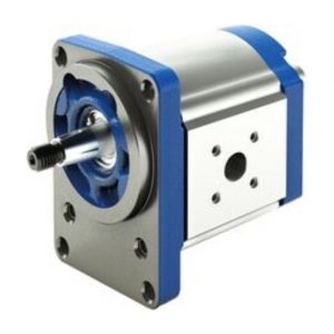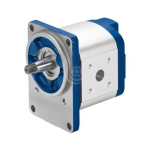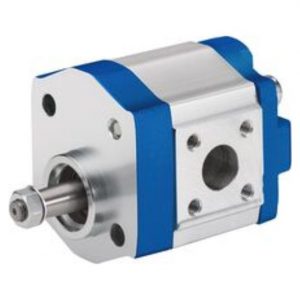

PV7-A
Hydraulic pumps, type PV7…A are direct controlled vane pumps with variable displacement. The basically comprise of the housing, cover, rotor, vanes, stator ring, pressure spring, adjustment screw and control plate. For limiting the maximum flow, the pump is fitted with an adjustment screw.
Product Description
The driven rotor rotates within the stator ring. The vanes which are guided in the rotor are pressed against the inner running surface of the stator ring by centrifugal force.
Suction and displacement process :
The chambers which are required for the transport of the hydraulic fluid are formed by the vanes, the rotor, the stator ring, the control plate and the cover plate.
The chamber volume increases as the rotor rotates and the chambers are filled with hydraulic fluid via the suction channel (S). When the largest chamber volume is reached, the chambers are separated from the suction side. As the rotor continues to rotate the connection to the pressure side is opened, the chambers decrease in size and force the hydraulic fluid into the system via the pressure port (P).
Pressure control:
The stator ring is held in its initial excentric position by spring. The maximum operating pressure required in the system is set at the adjustment screw via the spring. The pressure which builds up due to the work resistance acts on the pressure side of the inner running surface of the stator ring, against the force of the spring. When the relevant pressure is reached, which is determined by the set spring force, the stator ring is moved out of its excentric position in the direction of the zero position.
The flow adjusts itself to the value which is being demanded at that time. When the maximum pressure, which has been set at the spring, has been reached then the pump regulates the flow back to virtually zero. The operating pressure is maintained and only the case drain is replaced. Losses and heating of the hydraulic fluid is thereby minimized.